- en
INTEGRATION BOILERS
Series "Monza"
Emergency/Integration Boilers


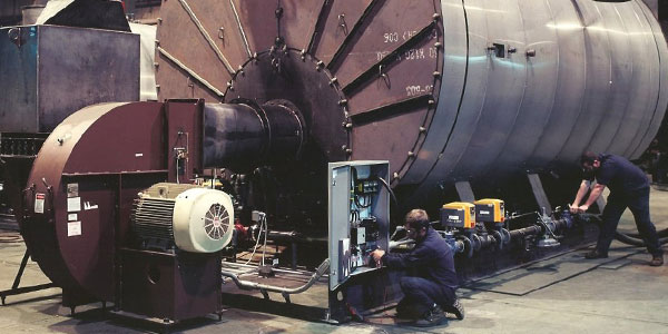
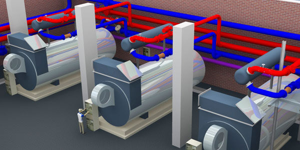
High performance Emergency/Integration Boilers designed and specialized for hot or overheated water district heating operation. Where possible, Emergency/Integration Boilers | Series Monzathese boilers can be implemented by a condensation module in order to increase the thermodynamic efficiency. Two construction types are provided: the first fire-tube and the second water-tube, depending on application. Boilers are equipped with shut-off valves, control and safety devices, as well as electrical control panel, regulation, monitoring and data transmission, and are ready for remote control and integration with existing monitoring systems on free and unified protocols as well.
This family of boilers completes the CHP plant on the heat production side, adding in to the power produced by the cogeneration recovery boilers. Another application is to help in case of CHP group maintenance.
- Thermal Power: 0.5 to 50 MWt.
- District Heating max Temperature: 135 ° C.
- Hydraulic Design: PN16.
- Overall max efficiency: 98%.
- Certifications: CE / PE as a whole.
Range
Mod. Monza
District Heating emergency or Integration boilers
| POS. | Model |
District Heating Thermal Power (MWt) |
Hydraulic Design |
Working Temp (°C) |
Efficiency (%) |
|---|---|---|---|---|---|
| 66 | Caldaia M - 500 | 0,5 | PN 10 ÷ PN 25 | 90 o 105 | 95 |
| 67 | Caldaia M - 750 | 0,75 | PN 10 ÷ PN 25 | 90 o 105 | 95 |
| 68 | Caldaia M - 1000 | 1 | PN 10 ÷ PN 25 | 90 o 105 | 95 |
| 69 | Caldaia M - 1500 | 1,5 | PN 10 ÷ PN 25 | 90 o 105 | 96 |
| 70 | Caldaia M - 2000 | 2 | PN 10 ÷ PN 25 | 90 o 105 | 96 |
| 71 | Caldaia M - 3000 | 3 | PN 10 ÷ PN 25 | 90 o 105 | 96 |
| 72 | Caldaia M - 4000 | 4 | PN 10 ÷ PN 25 | 90 o 105 | 96 |
| 73 | Caldaia M - 5000 | 5 | PN 10 ÷ PN 25 | 90 o 105 | 98 |
| 74 | Caldaia M - 7500 | 7,5 | PN 10 ÷ PN 25 | 90 o 105 | 98 |
| 75 | Caldaia M - 10000 | 10 | PN 10 ÷ PN 25 | 90 o 105 | 98 |
| 76 | Caldaia M - 15000 | 15 | PN 10 ÷ PN 25 | 90 o 105 | 98 |
| 77 | Caldaia M - 20000 | 20 | PN 10 ÷ PN 25 | 90 o 105 | 98 |

Working condition
| HOT WATER | SUPERHEATED WATER | COOLING | |
|---|---|---|---|
|
THERMAL DESIGN DISCTRICT HEATING CIRCUIT |
90/65°C | 115/65°C | 7/11°C |
|
MECHANICAL DESIGN DISCTRICT HEATING CIRCUIT |
PN16÷PN25 | PN16÷PN25 | PN16÷PN25 |
|
THERMAL DESIGN SUBSTATIONS SECONDARY CIRCUIT |
85/55°C | 85/55°C | 14/8°C |
|
NOMINAL PRESSURE LOSS SUBSTATIONS PRIMARY AND SECONDARY CIRCUITS |
10/3 w.c.m. | 10/3 w.c.m. | 10/3 w.c.m. |
|
FLUID SPEED DISCTRICT HEATING CIRCUIT |
0,5÷2 m/s | 0,5÷2 m/s | 0,5÷2 m/s |
| CENTRAL CONDUIT PUMPS HEAD | 0,5÷9 bar | 0,5÷9 bar | 0,5÷9 bar |
| PRESSURE LOSS POWER PLANT INNER CIRCUIT | 0,5÷1,5 bar | 0,5÷1,5 bar | 0,5÷1,5 bar |

