- en
BIOMASS CHP POWER PLANTS
Series "Brianza"
Biomass CHP Power Plants


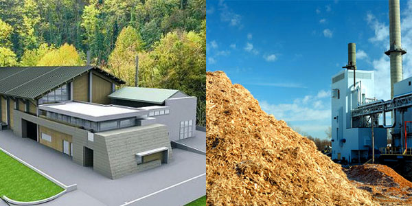
Electric and Thermal biomass (virgin wood chips) CHP Power Plants with steam production and expansion upon turbomachinery (Rankine steam cycle). Thermal energy throughout cogeneration process is controlled by steam bleeding. Possible integration of thermal energy can be accomplished by biomass boilers or traditional fuel. Power Plant model suitable for district heating plants with electrical power higher than 1 MWel. Electrical energy generated by this plant type is patronized through so-called "green certificates" for higher than 1 MWel powers and by all-inclusive tarif for powers under 1 MWel. District Heating is almost always required for authorize reasons and for a good profitability it shall not cost more than € 800.000,00 for each nominal MWt installed with 40% more selling thermal energy than that deliverable. Interesting integration between Brianza M module with Lombardia 2 and Piemonte 2 models.
- Electric Power 0,75 to 10 MWel.
- Thermal power: 1,5 to 100 MWt.
- Cycle: Rankine steam cogeneration.
- Fuel: virgin wood chips.
- Feasibility study reference: BRIANZA.
- Max electric efficiency: 15%
- Max overall efficiency: > 85%.
- Certification: CE / PED as a whole.
Range
Mod. Brianza
Biomass CHP (Rankine Steam cycle) power plants (virgin wood chips) with district heating module.
| POS. | Model |
Nominal Electric Power (MWel) |
Available Thermal Power (MWt) |
Max electric power district heating arrangement (MWel) |
Electric Efficiency MAX (%) |
Overall Efficiency (%) |
|---|---|---|---|---|---|---|
| 27 | Brianza 750 | 0,75 | 1,9 | 0,5 | 20 | 81 |
| 28 | Brianza 1000 | 1,3 | 3 | 0,8 | 20 | 81 |
| 29 | Brianza 2000 | 2,3 | 5,5 | 1,5 | 20 | 82 |
| 30 | Brianza 3000 | 2,9 | 7,1 | 1,9 | 21 | 82 |
| 31 | Brianza 5000 | 5 | 11,7 | 3,1 | 22 | 83 |
| 32 | Brianza 7500 | 7,5 | 17,6 | 4,6 | 23 | 83 |
| 33 | Brianza 10000 | 10 | 23,5 | 6,1 | 24 | 83 |
IMG For all the above mentioned models wood chips steam generator only is available, mod. Brianza M or Brianza 2 version for electric generation only.

Working condition
| HOT WATER | SUPERHEATED WATER | COOLING | |
|---|---|---|---|
|
THERMAL DESIGN DISCTRICT HEATING CIRCUIT |
90/65°C | 115/65°C | 7/11°C |
|
MECHANICAL DESIGN DISCTRICT HEATING CIRCUIT |
PN16÷PN25 | PN16÷PN25 | PN16÷PN25 |
|
THERMAL DESIGN SUBSTATIONS SECONDARY CIRCUIT |
85/55°C | 85/55°C | 14/8°C |
|
NOMINAL PRESSURE LOSS SUBSTATIONS PRIMARY AND SECONDARY CIRCUITS |
10/3 w.c.m. | 10/3 w.c.m. | 10/3 w.c.m. |
|
FLUID SPEED DISCTRICT HEATING CIRCUIT |
0,5÷2 m/s | 0,5÷2 m/s | 0,5÷2 m/s |
| CENTRAL CONDUIT PUMPS HEAD | 0,5÷9 bar | 0,5÷9 bar | 0,5÷9 bar |
| PRESSURE LOSS POWER PLANT INNER CIRCUIT | 0,5÷1,5 bar | 0,5÷1,5 bar | 0,5÷1,5 bar |

